


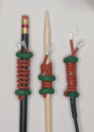
I wanted to create a simpler imitation of what is primarily a graft heating mechanism for nuts or grape grafting. One part at a time starting with the brown heat trace wire to the left which is wrapped to heat the sensor and the sensor itself is kind of a replica of a dormant graft and as actively demonstrated the rise is 30F.
<----- indoors ---
Note that this plus 30 degrees is the maximum value temperature in a control loop because underneath the green tape I adjusted the setpoint beyond the reach of our target temperature.
The small blackbox transformer is actual repurposed here from a 6 volt motorcycle battery charger. without the battery the output voltage keeps to within 7.2-7.5 volts and can adequately and very nicely feed up to 5 other 130 ohm brown heating wires. (more on materials later) The actual watts being loaded per wire wire is just under 0.4 watts which (engineering purposes) is roughly equivalent to my multimeter reading of ~52mA.
Another few design accomplishments (pros):
-no fluid, pumps etc. are involved in this one, but this is only beneficial for home purposes for several grafts a few at a time. Volume propagators will find patents that have already been established that cover heat/fluid systems better.
Disadvantages:
-since this will be done for mostly topworking purposes the wind is at some disadvatage here. For example when I forced air over the desk the temperature rise reduced to only +10F (~33%). This may not be an issue depending on your programmed range of target. Teflon tape application around the brown wire as an idea would stand up well to calm wind losses.
Materials: The Inkbird is kind of the command center. I use a wifi one which costs more than the exact same thing online by Inkbird for ~30 dollars. That's the biggest cost here. I will cover the basics of manufacturing the next most pricey item next.
The same brown wires at 13 inch lengths weigh in just right at ~130 ohms. They are not costly in and of themselves but due to the nature of the supplier I can't release which part or where to get what needs to be procured. In the case a manufacturer gets interested I would have no issues as long as I'm contacted privately. Those that I know that either want to borrow these inexpensive graft or cutting wrapping devices can use a few. To any interested parties then read on...
These won't last as long as they would were the cotton like materials inside to get wet so the best idea is vaseline or toilet bowl wax for keeping up with the final coating. I would recommend this just even on top of any parafilm (stated teflon by mistake) that may be put over top as explained above.
For any who seek other products and need to go elsewhere then understand that the chromium conductors are in need of soldering to a solder wick copper. This is the determination that really adds onto the material costs of each because a magnification and holding device become necessary, not to mention the wick and solderer etc. The reason why is seen here that the ends to grab are as small as hair;
Brown wire ends Closeups

Sandpapering nichrome wire at the intended soldering points is often recommended.
Perhaps there are small crimp-type connectors commonly available that would reliably connect
mechanically to the wire; especially if the wire end was folded over several times to increase the effective diameter.
Various Molex connectors are inexpensive.

Okay Rooney,
Now your email makes sense to me. I just finally replied and then saw this right after.
And coincidentally I've been e-shopping for a ratcheting terminal crimper having only crimped a few ever but finding a need for one twice now in the last few weeks.
My quick take away is that you are developing a mechanism to supply heat just near the graft union for cases where heat is required for the graft to callus, but you want to keep it localized to prevent breaking dormancy prematurely. You are creating a resistance heating element with the brown wire that you can custom wrap for each application and secure with those tough green O-rings or similar. You've found the components needed from other repurposed materials that you've adapted to provide the right amount of power to get an appropriate temperature rise.
I didn't understand what you and Larry were talking about the soldering until I saw the closeup picture. That is a tiny wire.
It is a small wire, but not an outlier among electronic conductors.
It would be interesting to know the actual gauge of the Rooney project wire.
I did much prototyping over the years using 30-gauge wire-wrap wire
and had to come up with ways to connect it to various non-wrap connectors.
My all-time record was soldering a 36-gauge sensor wire to a large metal drum.
jafar said
My quick take away is that you are developing a mechanism to supply heat just near the graft union for cases where heat is required for the graft to callus, but you want to keep it localized to prevent breaking dormancy prematurely. You are creating a resistance heating element with the brown wire that you can custom wrap for each application and secure with those tough green O-rings or similar. You've found the components needed from other repurposed materials that you've adapted to provide the right amount of power to get an appropriate temperature rise.
That IS what's documentated, yes !! (thanks)
Another general application is in breeding in further flung northern places having had winter lows go under -20F for any appreciable amount of time. For example Edmonton where they grow apricots in more wind protected zones but flower buds die. If a few flowers can be protected then seven of these could be placed out and set at -5F, which in the Inkbird is well within it's set-point range. Normally they achieve a crop once every 7 years. This way it's fairly well engineered for something like that to achieve new tree seedlings 100 percent of the time be it just a few vs. about 15 percent of the years.
I shall send them the permalink and soon will be up there for visiting purposes anyways. All of my background and training in electric and electronics is from there.
Here I might wonder what becomes if I were to find a way to temporarily put a similar device around the base of any fruit tree to get wood to slip (in about January?) for the goal of changing varietals (bark grafting in new scions) with the least amount of what might bother or kill the tree?
I'm certainly going to find out.
As far as what was stated earlier per Larry about the guage. The internet is our friend here.
..which is lighter guage than what we used.
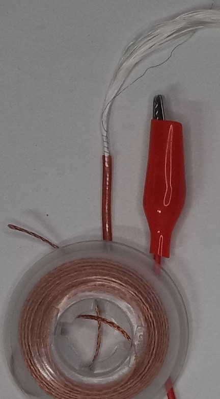
As seen to the left I had to unwind the candy cane and take resistance measurements to determine which size the manufacturer used here and came up with 47 ohms per foot. In the above link it equates to 38 guage. But according to this link it's slightly larger by ~about a guage.
Resistive values per guage of Nichrome wire
I overcame the problem of not having enough spring tension for the spring clips I use holding onto the element by using a product they sell at radio supply stores called Chem-Wik (copper roll to the left). It's hollow and thus fit for fattening up the connections for clips to hold. The element ends need to slip inside the hollow, then soldering at ~270F (won't burn isulation) or crimping using bare copper collars and a pressuring crimper. I obviously used the former and in several seconds of to limit heat and (with rosin-core) it soldered up.
The weak point now may be moisture wicking inside the brown jacket covering since it is an outdoors application. It is a good sign that these elements are pretty corrosian resistant and may not be adversly effected in longevity when rained on? 🙂
...this looks like an improved connection method.
I was wondering if you had tried inserting the heat element wire into the end of a multi-stranded wire, perhaps 18 or 16-gauge, bared of insulation up to 1/2", the larger wire held in a vice, only the bared portion protruding, everything is then held in place for soldering.
I had come across a table of wire vs gauge vs resistance-per-foot and am now wondering how "per foot" relates to the image above, where the resistance wire is closely spiraled in the assembly. The actual wire length then becomes nearly a factor of 3 longer than the whole assembled heating element (pi*D). Ohms-per-foot would be based on the literal resistance wire length rather than the length of the element assembly.
It could work with stranded wire but I used chem wik because I was familiar with it before.
When I measured the resistance that value I previously posted of 47 ohms is my element all uncoiled so compared to those resistance charts it really is 38 guage. 47 ohms checks out as 4 inches of brown wire and 12 or 13 inches of uncoiled wire with outer portion discarded. So from all sides it double checks out as 38 guage element wire.
Very few of us will use it though. People will if the few that see it manufactured as a clip on product per commented several days earlier, then it will. I'm wanting to get SweepBJames' ume apricot cutting rooted so I'm using mine now. Without these they had not worked 2 years ago. Will see.
Thanks James!
Idyllwild
jafar
Marsha H
Viron
1 Guest(s)